

The following is an adaptation of a simple dark detecting LED 'nightlight' circuit by 'evilmadscientist'.

http://www.evilmadscientist.com/article.php/nightlight
The way we've applied this circuit configuration is to the making of jewellery and as such a lot of twisting and bending of the components is required.


1 x 12.5 mm 3V coin cell battery
Step 3
Bend the other leg of the resistor around so that it meets the middle prong of the transistor (being careful not to connect the circuit accidentally). Solder together.

Step 4
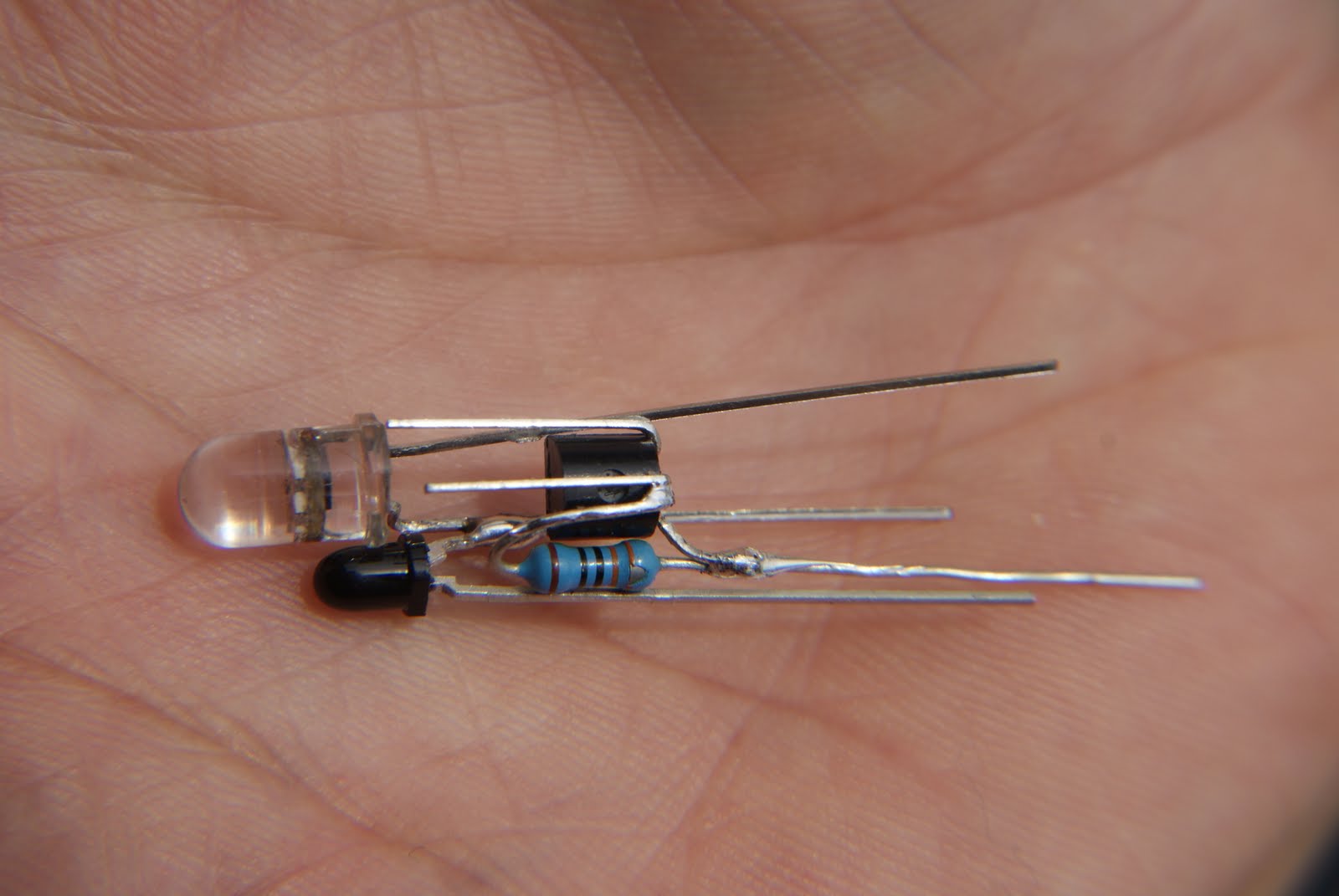
Bend the left-hand prong down parallel. This is the first component assembly. With the flat side of the transistor facing you, your first component assembly should look like this.


Step 6
Bend and precut legs to correct shape and length so that the - lead of the phototransistor lines up with the middle prong of the transistor and the + lead of the LED lines up with the left-hand prong of the transistor.


Jason and Seamus

http://www.evilmadscientist.com/article.php/nightlight
The way we've applied this circuit configuration is to the making of jewellery and as such a lot of twisting and bending of the components is required.
The mercury switch on the breadboard below is an addition to the earring circuit to add versatility to the design, via responsiveness to the environment as well as helping with power consumption when the switch is tilted at an inactive or active angle (ie. lying flat or at 90 degrees to the ground).

You will need the following components to make the dark detecting jewellery we demonstrate.

1 x 12.5 mm 3V coin cell battery
1 x 1K resistor
1 x polarized transistor (2N3904)
1 x polarized transistor (2N3904)
1 x LED (standard low voltage)
1 x mercury tilt switch
1 x photransistor IR (black/blue wrapper) that blocks out visible light (SFH 309 FA-4/5)
Step 1
splay transistor legs like so

Step 2
Solder resistor flush with left-hand side (when round side of transistor is facing you) of transistor so that the resistor leg pokes away from the transistor

Step 3
Bend the other leg of the resistor around so that it meets the middle prong of the transistor (being careful not to connect the circuit accidentally). Solder together.

Step 4
Bend the left-hand prong down parallel. This is the first component assembly. With the flat side of the transistor facing you, your first component assembly should look like this.

Step 5
Now we have to add the phototransistor and the LED. We will first solder them together as component assembly 2. We must solder the - terminal of the LED to the + terminal of the phototransistor. You may want to bend and trim the prongs as shown. Make sure the + lead of the LED and the - lead of the photo transistor sit further forwards than the join of the other two leads.
Now we have to add the phototransistor and the LED. We will first solder them together as component assembly 2. We must solder the - terminal of the LED to the + terminal of the phototransistor. You may want to bend and trim the prongs as shown. Make sure the + lead of the LED and the - lead of the photo transistor sit further forwards than the join of the other two leads.

Step 6
Bend and precut legs to correct shape and length so that the - lead of the phototransistor lines up with the middle prong of the transistor and the + lead of the LED lines up with the left-hand prong of the transistor.
Once you're satisfied it's all sitting flush and parallel, solder together.
Step 7
Bend + lead of phototransistor so that it runs directly up behind middle of the flat part of the transistor. This will function as the - terminal for your battery.

Step 8
The final component we need to add as the mercury tilt switch. Shorten the leads slightly so that you are able to play around with placement of the switch in relation to the coin cell etc.

Step 9
solder one lead from the tilt switch to the remaining lead of the resistor

Step 10
Bend the remaining lead from the tilt switch so that it sits flush with the back (flat part) of the transistor. This is your + terminal.

Step 11
Slot your coin cell in between your + and - terminals being careful that the battery does not touch any other edges.


Step 12
You are now ready to attach and loop, hook or hoop the top of the mercury switch to transform the circuit into jewellery.


Dip in resin or finish however you like.

Preferably a more exact and functional design for housing the battery would allow the owner to swap batteries with ease in the future. This would also allow the advantage of using rechargeables.
Have a play with arrangements and configurations and let us know what you come up with.
Have a play with arrangements and configurations and let us know what you come up with.

Enjoy.
Jason and Seamus
This is a great DIY stuff. I should do the same when I will arrange a party on my own or tell to my friends about it.
ReplyDeleteCalifornia Accessories